|
The Overdrive and SU Project... This is my attempt to install a Spitfire J-type overdrive into my MG Midget 1500. The tranny bolts right up, so that part is easy. However, the body was never meant to take it so there are some modifications to be made. This is a semi-common modification and I have emailed some people who have done it, but I have never actually seen a car with it done so some of this is playing by ear. The twin SU HS-4s make the car roughly UK-spec. Although cars in the UK came this way, it's a little more than a bolt-in conversion because the UK cars had the steering column through there and the whole area is different. The North American spec cars have a few obstructions that have to be removed. Post mortem: Now that it's all done and running, I have a lot of good things to say about the conversions. First of all the overdrive is predictably pretty darn nice, highway drives are now fairly peaceful and relaxed in OD 4th. It also works in third gear, but I don't expect I'll use that very much. Frankly, I find the disengaging of third overdrive a bit violent. If you aren't on the throttle enough the rear tires even chirp! I suspect this has a lot to do with the low weight of the car, similar to how a big car's automatic transmission has a lot easier time doing inaudible changes than an econobox. As for the SU conversion, that's a lot more subjective but there is a definite power gain and I believe a significant one. Around low RPMs it isn't noticeable, the car feels about the same as before. However at high revs it really does pull a fair bit harder. Nice for passing speed, especially when combined with an overdrive downshift! All of these images are thumbnails, click on the image to see a larger version. |
![[ Midget ]](pics/midget_overdrive.jpg) |
The wife his kindly informed me that I can never sell this car, so I guess I'll
have to make it into the super Midget. First step, here's a J-type overdrive
tranny that should make cruising a little smoother. The tranny was supplied
by Waterloo Drivetrain Systems,
then of Austin Texas but now in California. They
also have an incredible selection of five speed kits for many cars. Mine wasn't
a kit though, just the tranny. August 30th, 2000 |
|
![[ Midget ]](pics/midget_pulling_engine_1.jpg) |
First step is to pull the engine. First step in pulling the engine is
to unhook everything. Since the engine is coming out and staying together,
I left a few bits on it like the starter, alternator, fan, etc. September 1st, 2000 |
|
![[ Midget ]](pics/midget_pulling_engine_2.jpg) |
This is the inspection hole at the bottom. To remove the engine requires detaching
the driveshaft here, but this will become more important later, because this
area has to be modified. September 1st, 2000 |
|
![[ Midget ]](pics/midget_pulling_engine_3.jpg) |
This is the standard transmission from beneath. This engine is basically leak-free,
but because of the design of the engine it makes a horrible mess when you spin
the filter off. I had just changed the oil a few weeks ago and everything still
has a nice sheen of fresh oil. Yech. September 1st, 2000 |
|
![[ Midget ]](pics/midget_pulling_engine_4.jpg) |
This is the rig I use to pull engines. I have an overhead steel I-beam in
my garage that I rig up a cable hoist to. Although the car is actually
sitting on a four poist hydraulic hoist, I still find it easier to do
it the old way. (although the hoist is incredibly useful when I am doing
all the back and forth unhooking of engine bits in the engine bay, at
the tailshaft, the clutch slave, etc.) September 1st, 2000 |
|
![[ Midget ]](pics/midget_pulling_engine_5.jpg) |
...up a little... September 1st, 2000 |
|
![[ Midget ]](pics/midget_pulling_engine_6.jpg) |
...and finally we are clearing the engine bay. Because of the design of the
car the engine has to tilt at a severe angle to come out with the tranny
installed. It's not too big of a deal coming out but it really makes putting
it back a two person job. September 1st, 2000 |
|
![[ Midget ]](pics/midget_pulling_engine_7.jpg) |
...and we're out! Total time from driving it in to having the engine on
the floor, about 6 hours casual working including Pepsi breaks and photos. I
could probably do it in about 3 if I was in a rush and it wasn't the hottest
day of the year in a stuffy garage. September 1st, 2000 |
|
![[ Midget ]](pics/midget_pulling_engine_8.jpg) |
And here's what an engine bay looks like sans engine. I don't expect to do any detailing while it's out
but I sure intend to clean a bit. September 1st, 2000 |
|
![[ Midget ]](pics/midget_pulling_engine_9.jpg) |
...and again. The next part of the work will be done on the shop floor, I'll be
setting up the two transmission units side by side to measure all
of the differences and plan for the body mods. September 1st, 2000 |
|
![[ Midget ]](pics/midget_overdrive_day_two_1.jpg) |
Here is the original Midget transmission tunnel. There are two main hurdles with putting
the overdrive in here. The crossmember is in the way, and the tunnel is too narrow. The
general plan is to remove the crossmember and weld a new one in underneath, and second to make
the tunnel wider. September 2nd, 2000 |
|
![[ Midget ]](pics/midget_overdrive_day_two_2.jpg) |
Here are the two trannies side by side, overdrive on the right. You can see
why the tunnel needs widening, the overdrive is fat and placed right at the
back of the unit. September 2nd, 2000 |
|
![[ Midget ]](pics/midget_overdrive_day_two_3.jpg) |
Here are the units side by side. The normal tranny in the back shows the
transmission mount hanging at the back. This mount normally sits on the
crossmember. You can see the OD tranny bulge goes through this area, which
is why the crossmember has to go. September 2nd, 2000 |
|
![[ Midget ]](pics/midget_overdrive_day_two_4.jpg) |
Here is the inspection hole again, with two cuts made to remove the area
of the floorpan between it and the crossmember. September 2nd, 2000 |
|
![[ Midget ]](pics/midget_overdrive_day_two_5.jpg) |
With that area removed, we see the crossmember. The crossmember is a top-hat
section that becomes a closed section when welded to the floor part we just removed. September 2nd, 2000 |
|
![[ Midget ]](pics/midget_overdrive_day_two_6.jpg) |
Here is the cross member removed. It's only removed roughly at this stage, but
this will give enough room to test-fit the transmission and design the
new crossmember. It's a weird camera angle, the dark red I-beam in the background
is actually above the car, this is the beam I use to pull the engine. You can see
the chain still hanging there, waiting for the reinstall job. September 2nd, 2000 |
|
![[ Midget ]](pics/midget_overdrive_day_two_7.jpg) |
This is the tunnel with the crossmember removed, but still original size.
Notice that the tunnel on the left in this picture is vertical, and
the other side has a slight indent. I am not sure what the indent is for, it
might be a leftover design feature from the A-series engine/gearbox the Midget first
came with. The rubber bung in the picture is from that era, it goes nowhere. September 2nd, 2000 |
|
![[ Midget ]](pics/midget_overdrive_day_two_8.jpg) |
This seems to be the easiest way to stretch the transmission tunnel, a careful
application of a screw jack. If you had the body stripped to a bare shell
it might make sense to section out some metal and weld it back to give
more room. However, to do any welding on the sides of the tunnel I'd have to remove the
seats, carpets, and underpadding. This method works, although it's a bit
crude to watch. September 2nd, 2000 |
|
![[ Midget ]](pics/midget_overdrive_day_two_9.jpg) |
Here is the tunnel after the "procedure". This will now give
enough room for the overdrive unit. September 2nd, 2000 |
|
![[ Midget ]](pics/midget_overdrive_day_two_10.jpg) |
Here is the overdrive unit with the wiring done. I suppose it wasn't
an ideal situation to use red wire for the whole thing, but this was
the most time-and-weather-resistant wire I had. This wiring is not
very accessible when the tranny is in, so I want it to last. The extra
wire stuffed into the shifter hole will go to the switch. September 2nd, 2000 |
|
![[ Midget ]](pics/midget_overdrive_day_two_11.jpg) |
Here is the tranny back on the engine. I put a new clutch in during
this swap, always a good idea if you have the engine out since it's
such a pain to do. This is the end of day two, next up I'll be test
fitting the unit and getting the exact shape of the rear crossmember
down. September 2nd, 2000 |
|
![[ Midget ]](pics/midget_overdrive_day_three_1.jpg) |
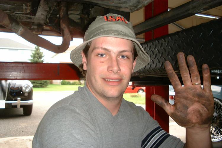
Here's me working the engine into the bay. It's always a tricky job
in this car, it's even trickier with the big OD hanging off the end. I
had a few extra hands today, that helped a lot. It also means I get to
be in a picture! September 3rd, 2000 |
|
![[ Midget ]](pics/midget_overdrive_day_three_2.jpg) |
Here is the underside view of the tranny installed, but with no rear
mount yet. I have a crowbar in the crossmember to hold the weight, and
the front mounts are stitched up. I think it's just a lot easier to
make a crossmember when you can see everything in place than to make
one from measurements, although others have done it. At this point the transmission is almost in the right place, the new mount will have to lift the transmission about 3/4" more to line everything up and to give the bellhousing a little more clearance from the chassis rails. The scratched lines in the underseal mark where the propshaft originally was, it appears I can use the same propshaft, it bolted on without trouble and I think there is still some sliding left. Between the scratches is the two mounting holes on the tranny. That's it for day three, a short day. (about 2.5 hours) September 3rd, 2000 |
|
![[ Midget ]](pics/midget_overdrive_day_three_3.jpg) |
A lot of this is made easier by the four-post hoist. Every garage needs one! In
all seriousness the hoist is great but you don't need one. If you can pull
and replace an engine you can do this swap. September 3rd, 2000 |
|
![[ Midget ]](pics/midget_overdrive_day_four_1.jpg) |
Here is the new crossmember. The relief slots are cut for the seat rail stiffeners,
and on this car, brake and fuel lines. This crossmember restores the body stiffness
lost when we cut out the original one, it doesn't touch the overdrive. September 4th, 2000 |
|
![[ Midget ]](pics/midget_overdrive_day_four_2.jpg) |
Here is the crossmember welded in. Also welded in are two short pieces coming
back from the crossmember. They will hold up the rear of the tranny. Be careful
if you do this with the carpets in, you will make some smoke. In this case, I
had an assistant on top keeping the carpets soaked with water. September 4th, 2000 |
|
![[ Midget ]](pics/midget_overdrive_day_four_3.jpg) |
This is my fabricated rear transmission mount. It's made from bar steel, and
the grommets are from a TR6 shock assembly I had sitting around. With a bit
of test fitting and hammering, you can design this so that the tranny is
centered in the tunnel and sits at the right height. September 4th, 2000 |
|
![[ Midget ]](pics/midget_overdrive_day_four_4.jpg) |
This is the finished assembly from below. September 4th, 2000 |
|
![[ Midget ]](pics/midget_overdrive_day_four_5.jpg) |
Close up from the rear. The rear tranny mount bolts in. I really wanted to
weld this in, it would have been faster and stronger. However, I believe this
piece will have to be removed to get the engine and tranny out again, since
the tailshaft has to go down before it can come forward. September 4th, 2000 |
|
![[ Midget ]](pics/midget_overdrive_day_four_6.jpg) |
Viewed from the front. The goofy nuts below the rubber grommets are just
there because the only bolts I had for this job were a little too
long. The threads in the transmission are coarse and the bolt shafts
are rather fat, so it isn't a size I had a lot to choose from in my
buckets. The thread peeking out there is for the speedometer cable,
another struggle for another day. September 4th, 2000 |
|
![[ Midget ]](pics/midget_overdrive_day_four_7.jpg) |
Again from the front. That's it for this area. I also painted this
up and sealed off all the box sections to help prevent rot. From
here on it's just putting the engine bay back together. I'll be
replacing a few dozen hoses along the way, the old ones were pretty
poor. September 4th, 2000 |
|
![[ Midget ]](pics/midget_overdrive_day_five_1.jpg) |
It's day five on the island, and the automotive tribal council voted the
ZS carb out. The twin SU carb set from the UK is a lot like the overdrive,
it bolts right up but the body needs modification to make it fit. Luckily
this time the modifications are very minor. You can see the scale of
the modication here. September 5th, 2000 |
|
![[ Midget ]](pics/midget_overdrive_day_five_2.jpg) |
Here is the modification. The easiest and fanciest way to do this is as follows. Cut out
a triangular section of the front part (the brace), and throw it away. Partially cut out the rear part (the top corner of
the footwell) making just two cuts and bend it over 180 degrees so it plugs the hole in the brace as shown
here. Nifty! (the red thing is a wet shirt in the footwell to protect the carpets
from sparks) September 5th, 2000 |
|
![[ Midget ]](pics/midget_overdrive_day_five_3.jpg) |
Here it is from the other side of the engine bay, the front of the car is to
the left. The pocket is actually not smooth, it has the ridge in the
middle. That's perfectly fine, the clearance is actually for two
different things. The front clearance is for the jet to come down
when the choke is on, the back clearance is for the rear carb float
bowl. September 5th, 2000 |
|
![[ Midget ]](pics/midget_overdrive_day_five_4.jpg) |
After this, I welded in some covers for the open cavities and painted
the area. This picture looks ugly, but I thought I'd include it anyways,
because I didn't include a picture of the painted and goobered
overdrive subframe and somebody emailed me and politely suggested
that I should probably paint and seal it! September 5th, 2000 |
|
![[ Midget ]](pics/midget_overdrive_day_five_5.jpg) |
Here's the view with the manifolds installed. Notice the rear
carb area and where it sits versus the pocket. Be sure to leave
extra room for when the engine moves around on it's mounts. Also visible
here is the blanking plug for the EGR valve hole, the EGR valve in
that position would interfere with the front carb jet when the
choke was pulled. September 5th, 2000 |
|
![[ Midget ]](pics/midget_overdrive_day_six_1.jpg) |
Here is the engine bay going back together. The fresh air hose on the far
side picked up some new duct tape on this day, it's really
had it and every time I touch it another hole appears. A new one
is in the cards. Important to note here is the location
of the overflow tank up beside the radiator, if your car originally
has it elsewhere it might have to be moved here to clear the front carb. September 7th, 2000 |
|
![[ Midget ]](pics/midget_overdrive_day_six_2.jpg) |
Here's the engine bay with the water hoses installed. Frankly, you can
make it look a lot better than this by using a fitted hose kit, but I
only had access to standard heater hose. With standard hose, you have
to make gentle curves and extra loops to be sure the hoses don't kink,
so the overall look is messy and overly busy. September 7th, 2000 |
|
![[ Midget ]](pics/midget_overdrive_day_seven_1.jpg) |
Here is the heat shield that came with the carbs, although a lot
of people don't use them. It's actually a nice piece, and it's shaped
just right to clear the obstacles like the EGR-plug hole. I suppose
it's to prevent vapour lock. September 8th, 2000 |
|
![[ Midget ]](pics/midget_overdrive_day_seven_2.jpg) |
Here is the entire engine bay, ready to go, carbs and hoses galore. At this point I
fired it up and it ran ok even without touching carb adjustments, so I went for
a drive to test it all out. The car ran and drive fine, but the overdrive was
very iffy. It would engage if I was just coasting, but as soon as I'd give it
any throttle at all it would slip back to regular drive. All sources pointed to
incorrect oil, so I had to stop here and wait for the stores to open. September 8th, 2000 |
|
![[ Midget ]](pics/midget_overdrive_day_eight_1.jpg) |
Success! The oil on the left is what I was using. The extreme pressure fancy additives are probably too slippery for the cone clutch to grab under power, and/or the additives are causing foaming that don't allow the overdrive to develop the 450psi it needs to engage. The oil on the right was what I bought to try instead, it's probably the most low-tech oil you can buy, and the overdrive worked great once I got this oil in. I don't intend to leave this oil in there for long, it works great for the overdrive but I am not too confident that it will protect my gearbox over the long term. So I have a bit of fine tuning to do but in the meantime I have overdrive! September 9th, 2000 |
|
![[ Midget ]](pics/midget_overdrive_making_lit_switch_1.jpg) |
The correct way to switch the overdrive is via a switch in the shift lever, but I am
having some delays getting mine. In the meantime, I decided to put a lit switch in
the console. I popped out the EGR service indicator light, and used it's hole. I wanted
the switch to light up with the overdrive was on, so I bought a WalMart lighted
switch and did some internal mods. September 13th, 2000 |
|
![[ Midget ]](pics/midget_overdrive_making_lit_switch_2.jpg) |
This shot and the above shot show the modified switch. I opened the switch and fished out one
lead from the internal light, and routed it to the end and cut a slot to reach it. In
this shot I soldered on a lead that I ran to ground. I also removed the third lead
for safety, since it would be exposed and live in the mess of wires behind the
console. September 13th, 2000 |
|
![[ Midget ]](pics/midget_overdrive_making_lit_switch_3.jpg) |
And here's how it looks in the car. (wow the car looks messy in this shot, and
the awful DPO radio with broken mountings doesn't help things) Whenever the ignition is on and the shift lever is in third or fourth, power is applied to one side of the switch. The other terminal is wired to the solenoid, and internal to the switch it's wired to the light. The other end of the light is fished out of the switch as shown above and grounded seperately. So, the switch is only lit when the overdrive is actually engaged. The mods on the switch were required because the original design of the switch is to be lit all the time. All in all, it works. I'm holding out for the real switch, but if I decide to stay with this I'd likely seek out a switch with a brighter light inside. September 13th, 2000 |
Related link, Guy Weller's Conversion story.
Also related, six images from Eddie Cole's conversion: 1 2 3 4 5 6